Archive for May 2012

Variable Speed DC Drive Application To Reduce Noisy Control Signals

VARIABLE SPEED DC DRIVE APPLICATION TO REDUCE NOISY CONTROL SIGNALS

Oil Exploration Rig Application
 

Mighty Module Wilkerson Instrument

Mighty Module

Specifications                   I/O Manual


A flat bed trailer was outfitted with a 150 KW generator, two variable speed DC motor drives, and the necessary mechanical equipment to allow computer control of the system as an oil exploration rig.

One motor drove the drill, the other drove the hoist. The variable speed drives were SCR inverters with rectifiers to provide a variable DC voltage to each motor. The system had electronic torque limiters.

The drilling operation was computer controlled and two computers output a total of 2 analog signals (motor speed) from digital to analog converters and monitored 4 analog signals from tachometers and torque limiters. Six of Wilkerson Instrument’s MM4380A Isolated DC Transmitters were used in the analog paths to provide isolation and prevent ground loops. The customer built these Rigs and leased them for oil exploration. The customer called for help when the system did not work properly.

All six analog signals had noise, from the SCR drives, imposed on the outputs of the MM4380A signal conditioners. The noise amplitude was as high as the full scale DC process signal.

A discussion with the customer revealed they always had severe noise problems with the rigs and the best they ever accomplished was to get the noise down to about 20% of the full scale DC signal. The rigs seemed to work satisfactorily with this noise level so they lived with it.

This rig was the first to be built where they had attempted to deal with the noise. The user of the rigs usually parked the rig on a dirt mound about 8 to 10 feet above the surrounding terrain. They drove a ground rod into the earth at the bottom of the mound and used this as the system ground for the rig.

The customer faxed Wilkerson Instrument Co. drawings of the wiring of the analog part of the controlled system. It was discovered that all analog signals were run in shielded pairs. The shields were connected to circuit common on the computer as well as the MM4380A. All of the shields were also connected to a common point on the electrical box that held all of the equipment. This box was connected to the system ground.

The customer agreed with our suggestion and rewired the shielded cables so the shield of each cable was connected only to the circuit common of the driven device. They were also disconnected from the common ground point (and each other). This simple change dropped the SCR noise to less than 1% of the full scale DC signal and the customer was delighted.

The cause of the noise can be read at:  WIRING FOR TROUBLE FREE SIGNAL CONDITIONING  PDF


Solutions provider for signal conditioning and process control instrumentation – Wilkerson Instrument Company Inc – Copyright 2012


Differential Pressure Measurement Across Liquid Filters in a Beverage Processing Plant

DIFFERENTIAL PRESSURE MEASUREMENT ACROSS LIQUID FILTERS IN A BEVERAGE PROCESSING PLANT

SYSTEM REQUIREMENT:

Measure the pressure drop across each filter in a bank of filters to determine when to switch to a fresh filter(s) so the clogged one(s) can be cleaned.

Provide electrical isolation between each input signal as well as between input to output to prevent noise pickup and noise from ground loops.

Wilkerson  Instrument Co. Products Used


Mighty Module Wilkerson Instrument

Mighty Module


Mighty Module Wilkerson Instrument

Mighty Module


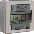
LP400 Loop Power Display

MM4408 MM4300 LP4OO
TWO-INPUT ISOLATED DC DIFFERENCE TRANSMITTER (OUTPUT = A – B) ISOLATED SIGNAL CONDITIONER LOOP POWERED DISPLAY
Specification PDF Specification PDF Specification PDF
I/O Manual PDF I/O Manual PDF I/O Manual PDF
How To Order How To Order How To Order


SYSTEM SYNOPSIS

Many beverage processing plants utilize filters at various stages of the process to remove unwanted materials from the liquid. As these filters load up doing their job, the flow passing through the filter is reduced. If the filters are not replaced or cleaned, the flow can be impeded enough to disrupt the total process.

This particular application surfaced when the customer was faced with replacing an old pneumatic system. The customer wanted to install an electronic system using strictly “off-the-shelf” commercially available equipment. He was faced with very limited control panel space and limited budget. Therefore, the system must use the fewest components possible and the smallest displays available.

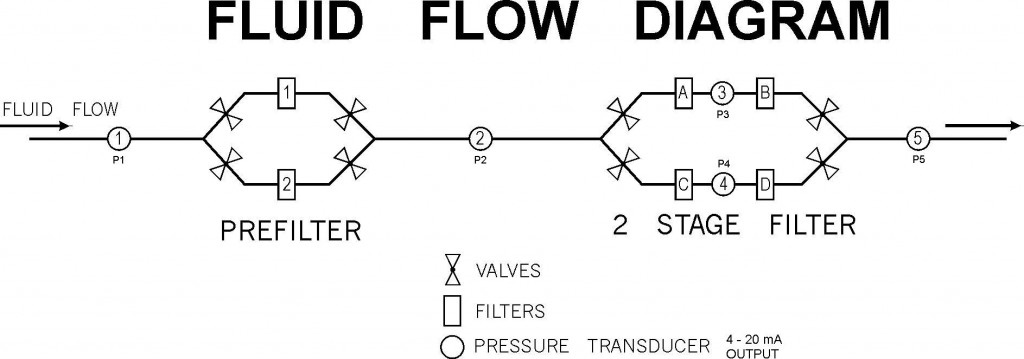
The Fluid Flow Diagram shows the basic arrangement of the pressure transducers and the filters. Only one prefilter and one two-stage filter are in service at any given time.


Fluid Flow Diagram - Bottling Plant

Fluid Flow Diagram - Bottling Plant


This allows the other filter(s) to be cleaned, sterilized and made ready for service.

USDA approved pressure transducers that are cleaned and sterilized in place were selected. By placing transducers 1, 2 and 5 so their use is common to either prefilter and either filter bank in use, the customer needed only five pressure transducers to do the job.

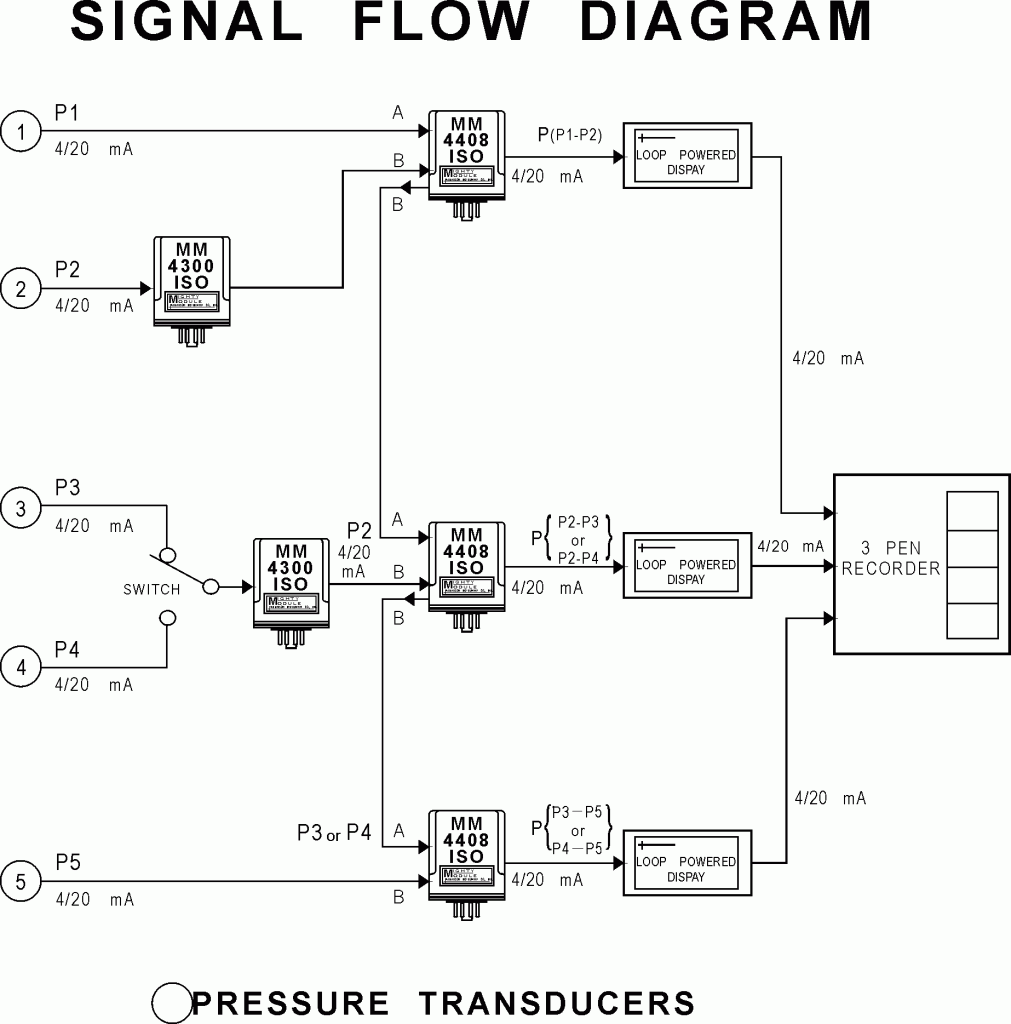
The Signal Flow Diagram shows how the customer’s judicious use of a switch, two MM4300 DC to DC transmitters, and three MM4408 difference transmitters achieves the needed input to input and input to output signal isolation with only five modules.

Signal Flow Diagram

Signal Flow Diagram

SOLUTION

The product chosen to measure the differential pressure (pressure drop) across the filter was the MM4408 and the MM4300.

The MM4408 inputs are not isolated from each other, but the output is isolated from both inputs.

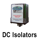
The MM4300 signal conditioner has isolation from the input to output.  It is used to provide one input to the MM4408. This provides isolation for both inputs.

Three LP400 loop powered displays in series with the three 4/20mA outputs provides an indication of the pressure on the output of the filters.  The Display can be calibrated in engineering units to fit the need.

Wilkerson Instrument Company Inc Is a solutions provider for signal conditioning and process control instrumentation  –   Copyright 2012


Follow

Get every new post on this blog delivered to your Inbox.

Join other followers: