Frequency Input Two Wire Transmitters
Frequency input 2W transmitters are widely used with flow meters to measure flow rate and total flow for a period of time. They are used in many other applications to measure the rate of movement of many other devices.
Typical Applications:
Flow meters
- Turbine meters
- Paddle wheel meters
- Positive displacement meters
Conveyor belt speed
Fan motor speed
AC generator speed for correct frequency
Speedometer for boats, trains, and other vehicles
Wind velocity
Applications are only limited by the creativity of the human mind. Creativity is improved by knowing how an intended useable device works.
HOW FREQUENCY INPUT 2 WIRE TRANSMITTERS WORK.
ANALOG CIRCUITS
Frequency input TX’s come in analog circuits and digital circuits. Analog circuits came first and are still in great use.
An analog frequency circuit works on a simple principle. A pulse of a fixed width and amplitude is created in a circuit which is triggered by the zero crossing of the input signal. The width is narrower than the period of 1 cycle of the input frequency.
As the input frequency changes, the rate of these pulses changes with the frequency. The circuit measures the average DC voltage created by these pulses. At the highest frequency measured, the voltage is at its highest level. As the frequency goes down, the average voltage gets less in proportion to the decrease in frequency. This circuit is the frequency to DC converter.

Average VDC Frequency
The output of the frequency to DC converter drives the TX output circuit to give 4mA at zero frequency and 20mA at the full scale frequency.
The frequency to DC converter circuit output has to be filtered to make the output a smooth DC voltage.
The filter used can only work to a limited lower frequency below the full scale frequency. As the frequency goes down, ripple on the DC voltage gets higher and higher.
Due to the filter limitations, the TX can only be used from full scale down to where the ripple becomes excessive.
The filter also limits the response speed of the TX to a change in input frequency.
The filter can be modified to improve response speed and ripple by having the frequency to DC converter circuit create a pulse for each zero crossing of the input signal. This provides 2 pulses per 1 cycle of the input. The filter can be faster because it is filtering a frequency 2 times higher.
The double pulse circuit requires a reasonable duty cycle on the input signal, because it must respond to 2 zero crossings.
The single pulse circuit can measure the frequency of a very narrow pulse, since it only responds to 1 zero crossing per cycle.
HOW FREQUENCY INPUT 2W TRANSMITTERS WORK.
DIGITAL CIRCUITS
First – Some Math and a Counter
The period of 1 cycle of a frequency signal is: (1000 Hz (1KHz) used as example)
Period = 1/freq Period = 1/1000 = .001S = 1 millisec = 1mS
If you open a gate into a counter for 1mS and let a 1,000,000 Hz signal go through the gate for the 1mS, the counter will display a count of 1000. This is our TX input signal (1000 Hz).
A digital Frequency 2W TX processes input signals by the counter method above. The input signal is divided by 2 to make a pulse the width of 1 cycle of the signal. This pulse opens the gate to the counter in the microprocessor. A clock generator (1,000,000 Hz in our example) pulses are counted for the time the pulse holds the gate open.
The count made is scaled mathematically so the resulting number can be input into a digital to analog converter. The analog signal from the A/D converter drives the output circuit to create a signal between 4mA to 20mA.
The A/D converter holds this value until the next sample is made. It is then updated to the new measured value.
The microprocessor allows a display to be part of the 2W TX. It also allows the frequency range to be changed with a keypad.
The lowest frequency which can be easily measured is limited by the size of the counter in the microprocessor and the size of the registers used for the math required.
SR2700 FREQUENCY INPUT TWO WIRE TRANSMITTER — WHAT IT CAN DO
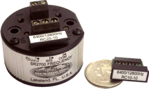
SR2700 Frequency Input Field Rangeable Two-Wire Transmitter
Most Frequency input 2W TX are purchased with a fixed frequency operating range. If the installation changes the device being measured, a different TX must be acquired.
INPUTS
The SR2700 can accept several inputs.
The most common signal source is a magnetic pickup which creates an AC sine wave when an iron object is moved passed the magnetic end of the sensor. The frequency of the sine wave created is proportional to the velocity of the iron passing the sensor. The TX creates an output current proportional to the frequency created. The common current used is a 4mA to 20mA output. Over current protection is provided.The TX input also has a pullup resistor which can create an input to the TX by pulling the resistor to common circuit and then releasing the resistor.
Breaking a light beam or a high speed switch closure can be used. Transistors can be used to drive the TX input with suitable signals driving the transistor. Creativity can add more.
A typical signal is a sine wave. Square waves can be processed. The time between narrow pulses, which are proportional to the frequency, can be processed. The input which can process the fore mentioned signals will also process an AC signal riding on a DC voltage.
The SR2700 can be changed to a different frequency input in the field. The frequency range and the filters required are in a small module which plugs into the top of the enclosure.
The small plug-in module on the SR2700 contains all the components to make the width of the square wave pulse (Full Scale) and the filters for a 20 to 1 or a 10 to 1 turn down. 10 modules cover the Full Scale range from 12.5Hz to 12,800Hz. One TX can cover any Full Scale in this frequency range with the small plug-in Module.
The product has the standard 4 to 20mA output.
It is available as a Private Label product.

DIS 975 Frequency Input Process Indicator with Optional Alarm(s) and Isolated Transmitter, 4.5 Digits

MM1700 Frequency Input, Single Alarm, Fixed Range, DPDT Relay
© Joe E. Wilkerson 2012