RTD 2 Wire Transmitters and how they work
An RTD (Resistance Temperature Detector) is a metal which changes its electrical resistance when its temperature changes.
The most common metal used for precision resistance measurements is platinum. Platinum is chosen because it is a noble metal which is stable, corrosion resistant, does not oxidize readily, and is easily workable into thin wire.
Copper is also used as an RTD. Because of its low resistance value, RTD’s of copper are low in ohms value and requires accurate measurements of the resistance when used as an RTD.
Because copper wire changes resistance with temperature and it is used to connect the RTD to the Transmitter, lead length between the RTD and the 2W Transmitter must be taken into consideration.
RTD SENSOR
Three versions of RTD’s compensate for lead length between the RTD and the Transmitter.
The signal from the RTD is typically developed by having a constant current flow through the RTD and the voltage across the RTD is measured to determine the resistance of the RTD.
Resistance = Voltage/Current.

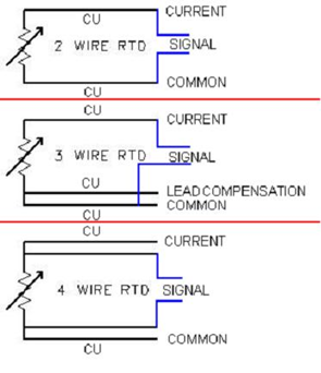
RTD Wiring Diagram
2 WIRE – Current flows through the RTD. The signal is the voltage drop across the RTD. The Cu leads must be short enough so their resistance change does not create a serious error in the measurement.
3 WIRE – Same as the 2 Wire except a Cu lead is brought from the RTD bottom to the TX. It allows the voltage dropped by the Common Cu lead to be measured. This voltage is doubled and subtracted from the signal voltage. This negates the voltage drop in the Common and Current Cu leads.
4 WIRE – The signal Cu leads go directly to the RTD. They allow the voltage across the RTD to be measured without the Current and Common Cu leads having any effect. This is the desired RTD setup for the most accurate measurement, when Cu leads could be a problem due to their length.
The transmitter has to be well designed so it does not have its current source, which excites the RTD, drift with ambient temperature changes. The circuits which process the signals must also be stable.
RTD’s are not perfectly linear with resistance vs temperature. Platinum RTD’s can be compensated. If the Transmitter is an analog design, linearization is accomplished by feeding a small amount of the RTD signal back to the current source which excites the RTD. This feedback increases the current a little for every positive change in temperature. With proper compensation very high accuracy can be obtained.
Microprocessor based Transmitters can manage Cu leads in a similar fashion to the analog version, but the add/subtract math is done by the microprocessor.
Linearization can be done more accurately with a microprocessor utilizing a lookup table of values.
© Joe E. Wilkerson 2012

